February 3, 2020
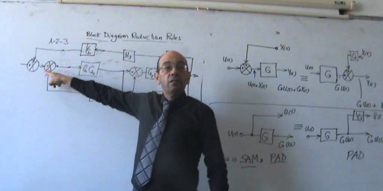
Block diagram in control system
What Is A Block Diagram?
E(s) = U(s) - Y(s)
This relationship is for the summer/subtractor (shown with a green circle)
W(s) = K(s)E(s)
This shows how W(s) - the control effort that drives the system being controlled, G(s) - is related to the error. The controller is probably an amplifier - probably a power amplifier - that provides an output to drive the plant, G(s).
Y(s) = G(s)W(s)
This shows how the output, Y(s), is related to the control effort that drives the plant (system being controlled ) with a transfer function, G(s).
Next, you can combine all of those relationships and get an overall relationship between the input and the output in the system. Here is the process.
Note that Y(s) = G(s)W(s)
Note that W(s) = KE(s), and use that in the equation for Y(s). That gives you:
Y(s) = G(s)W(s) = G(s)KE(s)
Note that the error is given by E(s) = U(s) = Y(s), and use that in the equation for Y(s).
Y(s) = G(s)W(s) = G(s)KE(s) = G(s)K[U(s) = Y(s)]
Now, solve for Y(s), and you get:
Y(s) = U(s)KG(s)/[1 + KG(s)]
That's what you need to know, and the final relationship will allow you to compute the output given knowledge of the system components and the input.
The plant being controlled includes a pump motor. The output is the height of a liquid in a tank.
It takes some threshold voltage on the pump to get it started. After the voltage exceeds the threshold, the flow rate into the pump depends upon the amount by which the threshold is exceeded.
In the block diagram model above, the threshold voltage (VT)and attendant effects are modelled using another summer.
The controller has a transfer function, GC(s).
The sensor has a transfer function, GS(s).
We can write the mathematical relationships that exist in this block diagram.
Y(s) = GP(s)[W(s) - VT(s)]
Y(s) = GP(s)[GC(s)E(s) - VT(s)]
Y(s) = GP(s)[GC(s)(U(s) - GS(s)Y(s)) - VT(s)]
Y(s) = U(s)GP(s)GC(s)[1 + GP(s)GC(s)GS(s)] - VT(s)GP(s)[1 + GP(s)GC(s)GS(s)]
Now, notice that the output has two components. One of those components is due to the input - something we know about. The other component of the output is due to the threshold voltage - something we might not have expected.
Block diagrams are ways of representing relationships between signals in a system. Here is a block diagram of a typical control system. Each block in the block diagram establishs a relationship between signals.
What if you have a more complex system? Here is a block diagram of a slightly more complex system.
A description of this system is as follows.
What do we make of all this? Actually, representing offsets and thresholds like this is a particularly good way to incorporate some simple nonlinearities into our block diagram algebra even though the block diagram representation was originally used only for linear systems. It's not hard to incorporate those offsets into your analysis. Here's what you can do.
Share this article
Related Posts


Latest Posts


