Open loop speed control
 DC Motor is very extensively used machine where the speed control is desired. The operation of DC motor in different steps is easy compared to AC motors. By the open loop control the DC motor can be operated at any intermediate speed by changing the voltage, armature current etc. But in open loop (Prediction based) control accuracy in speed cannot be obtained i.e. the speed will not be constant for load variations on the motor. There will not be any feedback to the controller to indicate the change in speed due to load. This disadvantage restricts the use of opes loop speed control DC motor in applications where constant speed is essential.
To avoid this disadvantage a closed loop technique is implemented where the output measured speed is fed back to the speed controller. In closed loop controller the speed can be maintained by adjusting terminal voltage according the speed difference caused by the load torque. I.e. a fine control of speed can be obtained using closed loop speed control. The below figure shows the basic block diagram of closed loop speed control.
The measured speed at the motor shaft is fed back and compared with reference speed. The difference speed error is applied to the speed controller to generate a control voltage Vc which controls the power converter and produces the desired terminal Vt .This terminal voltage controls the speed of the motor and thus the speed of the motor can maintained for any variations in the load torque. For example if the load torque has been increased, due to this high load the motor speed reduces momentarily from its desired value.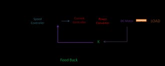 Thus the speed error at the output of the comparator increases which increases the control signal Vc. The speed controller can be proportional(P) or proportional integral(PI) and it also takes care of the maximum speed limit of the motor. This control signal decreases the firing angle of the thyristor if it is phase controlled converter or it increases the duty cycle to increase the switching On time if it is a chopper converter and thus the output terminal voltage will increase. This increased terminal voltage (armature voltage) develops more torque to compensate the effect of load torque and to maintain the constant speed.The same operation in the reverse way will be performed if the load torque reduces. When the applied torque matches the load torque then the motor speed will be constant. There will be small oscillations during this control which can be reduced by the perfect controller time constant.
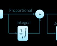
Share this article
Related Posts

Latest Posts


