Electro hydraulic control system
 In a departure from conventional wisdom, motion control can be implemented to increase production rate and product quality and consistency - all at the same time.
Motion control is the simultaneous control of acceleration, velocity, and position for performing a useful task. The critical concept in this statement is that all three variables — acceleration, velocity, and position — are under control. A review of some basic electrohydraulic designs will help pave the way to understanding the concepts of motion control. Two conventional hydraulic circuits will be used to illustrate the point: discrete, or so-called bang-bang directional control, and open-loop proportional control.
These two circuits will lead us to an ultimate solution: the electrohydraulic positional servomechanism. It will be shown that when the electrohydraulic servo is properly designed — and the control system is suited to the task — the result is a true motion control system meeting the divergent goals of increasing machine productivity and product quality, while reducing overall production costs.
Hydraulic system designers should realize early in the design process that a power unit providing constant pressure to the control valve is best suited to the motion control task. The ISO symbol for a constant pressure source, along with a plot of its behavior, is shown in Figure 1. A real-world constant-pressure source is shown schematically in Figure 2. It normally consists of a pressure-compensated pump augmented by large accumulators to accommodate the sudden flow demands of a servo or proportional valve and a check valve to prevent the pump from having to cross over center in order to absorb any flow that might otherwise be forced back into the pump.
Figure 2 also shows the pressure-flow characteristics of a conventional pressure-compensated pump. At low pressure, it behaves as a fixed-displacement pump, delivering nearly constant flow, neglecting internal leakage. When pressure reaches the knee value, PK, the pump's pressure compensator becomes active, and the displacement automatically decreases with rising pressure. Thus, at pressures above PK, the pressure-compensated pump acts very nearly as a constant-pressure source. It certainly is safe to deadhead this pump with closed-center valves without danger of overpressurization.
 Discrete control
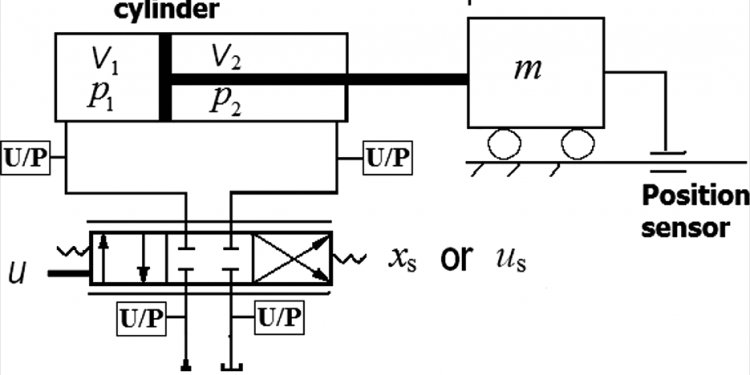
In a conventional electrohydraulic control system, Figure 3, a simple, solenoid-operated directional control valve can operate in only three discrete states: centered (off), shifted to the right to route flow in one direction, or shifted to the left to route flow in the opposite direction.
To understand the problems, imagine that limit switch LS1 in Figure 3 is closed, the right-hand solenoid is energized, and the cylinder is moving the load to the right at a speed determined by the supply pressure and the valve flow coefficients. At some point, the load engages the limit switch, which causes the directional valve to center and thus block all ports. The load will decelerate rapidly, subject to its mass, the cylinder's size, and how quickly the control valve shifts. Severe shock and vibration can occur before the load actually stops, especially if the load mass is great.
In the event of large shocks, machine members experience high stress levels that can shorten their lives. Very high pressure peaks — or spikes as they are frequently called - also will occur. These pressure peaks can overstress the hydraulic components, including the cylinder tube and seals, leading to premature leakage and failures. The external vibration can move the entire machine, putting mechanical stresses on the plumbing, which can lead to fitting failure.
In the oscillatory stopping process, the frequency of the vibration can be measured if one has force, pressure or speed sensors whose outputs can be displayed on an oscillographic recording instrument. With the recording, the frequency of the vibration can be measured. This frequency is called the hydromechanical resonant frequency (HMRF), and can be calculated using any of several methods. (Space limitations prohibit discussing HMRF in detail, but for more information on this important topic, see this article from the author.)
The potential for self-destruction is probably the biggest shortcoming of the discrete control system. However, poor repeatability of the stopping point can also be a serious drawback. When system designers use a limit switch to initiate deceleration, they normally do it because the application needs to stop the load at some predictable and controlled position. Unfortunately, in the discrete system, several random effects cause considerable variation in the ultimate stopping point. The actual stopping time is a complex function of:
- magnitude of the load's mass,
- shift time of the valve,
- timing of the land shut-off within the valve,
- valve internal leakage,
- cylinder internal leakage,
- friction in the cylinder and load,
- fluid viscosity, and
- scan time of the digital controller (PLC) if used.
AC solenoids produce valve shift times that are affected by the instant within the AC power line 60- or 50-Hz sine wave when switching takes place. The random variation in shift time of the valve will be at least the time of one-half a line cycle (8.3 msec in the 60-Hz system or 10 msec in the 50-Hz system). This adds to the normal random variations in the valve shift time.
Load and cylinder friction also contribute random variations. These are affected by system temperature, as is the viscosity of the process fluid, which imposes its own variations into the stopping time. If a digital controller is used, the random variation in stopping time will be at least equal to one full scan interval. The slower the digital controller, the greater the variation. The net result is that when the system of Figure 3 is tested for repeatability, the actual stopping point will vary considerably from trial to trial.
Share this article
Related Posts


Latest Posts


