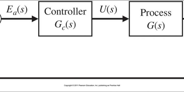
Feedback control system Block diagram
 The block diagram is to represent a control system in diagram form. In other words practical representation of a control system is its block diagram. It is not always convenient to derive the entire transfer function of a complex control system in a single function. It is easier and better to derive transfer function of control element connected to the system, separately. The transfer function of each element is then represented by a block and they are then connected together with the path of signal flow. For simplifying a complex control system, block diagrams are used. Each element of the control system is represented with a block and the block is the symbolic representation of transfer function of that element. A complete control system can be represented with a required number of interconnected such blocks. In the figure below, there are two elements with transfer function Gone(s) and Gtwo(s). Where Gone(s) is the transfer function of first element and Gtwo(s) is the transfer function of second element of the system.
In addition to that, the diagram also shows there is a feedback path through which output signal C(s) is fed back and compared with the input R(s) and the difference between input and output E(s) = R(s) – C(s) is acting as actuating signal or error signal. In each block of diagram, the output and input are related together by transfer function. Where, transfer function where, C(s) is the output and R(s) is the input of that particular block. A complex control system consists of several blocks. Each of them has its own transfer function. But overall transfer function of the system is the ratio of transfer function of final output to transfer function of initial input of the system. This overall transfer function of the system can be obtained by simplifying the control system by combining this individual blocks, one by one. Technique of combining of these blocks is referred as block diagram reduction technique. For successful implementation of this technique, some rules for block diagram reduction to be followed. Let us discuss these rules, one by one for reduction of block diagram of control system.
If the transfer function of input of control system is R(s) and corresponding output is C(s), and the overall transfer function of the control system is G(s), then the control system can be represented as
Take off Point of Block Diagram
when we need to apply one or same input to more than one blocks, we use take off point. A point is where the input gets more than one paths to propagate. This to be noted that the input does not get divided at a point, hence input propagates through all the paths connected to that point without affecting its value. Hence, by take off point same input signals can be applied to more than one systems or blocks. Representation of a common input signal to more than one blocks of control system is done by a common point as shown in the figure below with point X.Cascade Blocks
When several systems or control blocks are connected in cascaded manner, the transfer function of the entire system will be the product of transfer function of all individual blocks. Here it also to be remembered that the output of any block will not be affected by the presence of other blocks in the cascaded system. Now, from the diagram it is seen that, Where, G(s) is the overall transfer function of cascaded control system.Share this article
Related Posts
Latest Posts


