Feedback control Block diagram
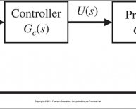
Figure 8 shows basic elements of a feedback control system as represented by a block diagram. The functional relationships between these elements are easily seen. An important factor to remember is that the block diagram represents flowpaths of control signals, but does not represent flow of energy through the system or process.
Below are several terms associated with the closed-loop block diagram.
The plant is the system or process through which a particular quantity or condition is controlled. This is also called the controlled system.
The control elements are components needed to generate the appropriate control signal applied to the plant. These elements are also called the “controller.”
The feedback elements are components needed to identify the functional relationship between the feedback signal and the controlled output.
The reference point is an external signal applied to the summing point of the control system to cause the plant to produce a specified action. This signal represents the desired value of a controlled variable and is also called the “setpoint.”
The controlled output is the quantity or condition of the plant which is controlled. This signal represents the controlled variable.
The feedback signal is a function of the output signal. It is sent to the summing point and algebraically added to the reference input signal to obtain the actuating signal.
The actuating signal represents the control action of the control loop and is equal to the algebraic sum of the reference input signal and feedback signal. This is also called the “error signal.”
The manipulated variable is the variable of the process acted upon to maintain the plant output (controlled variable) at the desired value.
The disturbance is an undesirable input signal that upsets the value of the controlled output of the plant.
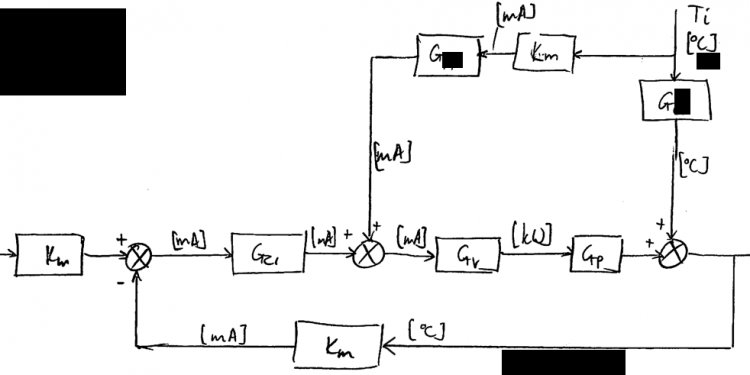
Figure 9 shows a typical application of a block diagram to identify the operation of a temperature control system for lubricating oil. (A) in Figure 9 shows a schematic diagram of the lube oil cooler and its associated temperature control system.
Lubricating oil reduces friction between moving mechanical parts and also removes heat from the components. As a result, the oil becomes hot. This heat is removed from the lube oil by a cooler to prevent both breakdown of the oil and damage to the mechanical components it serves.
The lube oil cooler consists of a hollow shell with several tubes running through it. Cooling water flows inside the shell of the cooler and around the outside of the tubes. Lube oil flows inside the tubes. The water and lube oil never make physical contact.
As the water flows through the shell side of the cooler, it picks up heat from the lube oil through the tubes. This cools the lube oil and warms the cooling water as it leaves the cooler.
The lube oil must be maintained within a specific operating band to ensure optimum equipment performance. This is accomplished by controlling the flow rate of the cooling water with a temperature control loop.
The temperature control loop consists of a temperature transmitter, a temperature controller, and a temperature control valve. The diagonally crossed lines indicate that the control signals are air (pneumatic).
The lube oil temperature is the controlled variable because it is maintained at a desired value (the setpoint). Cooling water flow rate is the manipulated variable because it is adjusted by the temperature control valve to maintain the lube oil temperature. The temperature transmitter senses the temperature of the lube oil as it leaves the cooler and sends an air signal that is proportional to the temperature controller. Next, the temperature controller compares the actual temperature of the lube oil to the setpoint (the desired value). If a difference exists between the actual and desired temperatures, the controller will vary the control air signal to the temperature control valve. This causes it to move in the direction and by the amount needed to correct the difference. For example, if the actual temperature is greater than the setpoint value, the controller will vary the control air signal and cause the valve to move in the open direction.
This results in more cooling water flowing through the cooler and lowers the temperature of the lube oil leaving the cooler.
(B) in Figure 9 represents the lube oil temperature control loop in block diagram form. The lube oil cooler is the plant in this example, and its controlled output is the lube oil temperature. The temperature transmitter is the feedback element. It senses the controlled output and lube oil temperature and produces the feedback signal.
The feedback signal is sent to the summing point to be algebraically added to the reference input (the setpoint). Notice the setpoint signal is positive, and the feedback signal is negative. This means the resulting actuating signal is the difference between the setpoint and feedback signals.
The actuating signal passes through the two control elements: the temperature controller and the temperature control valve. The temperature control valve responds by adjusting the manipulated variable (the cooling water flow rate). The lube oil temperature changes in response to the different water flow rate, and the control loop is complete.
Share this article
Related Posts
Latest Posts


