Types of closed loop control system
Why input, output and other signals are represented in Laplace form in a control system?
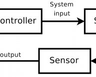
It is not necessary that output and input of a control system are of same category. For example, in electric motors the input is electrical signal whereas the output is mechanical signal since electrical energy required to rotate the motors. Similarly in an electric generator, the input is mechanical signal and the output is electrical signal, since mechanical energy is required to produce electricity in a generator. But for mathematical analysis, of a system all kinds of signals should be represented in a similar form. This is done by transforming all kinds of signal to their Laplace form. Also the transfer function of a system is represented by Laplace form by dividing output Laplace transfer function to input Laplace transfer function. Hence a basic block diagram of a control system can be represented as Where, r(t) and c(t) are time domain function of input and output signal respectively.Definition of Transfer Function
The transfer function of a control system is defined as the ration of the Laplace transform of the output variable to Laplace transform of the input variable assuming all initial conditions to be zero.Procedure for determining the transfer function of a control system are as follows
- We form the equations for the system
- Now we take Laplace transform of the system equations, assuming initial conditions as zero.
- Specify system output and input
- Lastly we take the ratio of the Laplace transform of the output and the Laplace transform of the input which is the required transfer function
- Block diagram method : It is not convenient to derive a complete transfer function for a complex control system. Therefore the transfer function of each element of a control system is represented by a block diagram. Block diagram reduction techniques are applied to obtain the desired transfer function.
- Signal Flow graphs : The modified form of a block diagram is a signal flow graph. Block diagram gives a pictorial representation of a control system . Signal flow graph further shortens the representation of a control system.
Poles and Zeros of Transfer Function
Generally a function can be represented to its polynomial form. For example, Now similarly transfer function of a control system can also be represented as Where, K is known as gain factor of the transfer function. Now in the above function if s = z1, or s = z2, or s = z3.s = zn, the value of transfer function becomes zero. These z1, z2, z3.zn, are roots of the numerator polynomial. As for these roots the numerator polynomial, the transfer function becomes zero, these roots are called zeros of the transfer function. Now, if s = p1, or s = p2, or s = p3.s = pm, the value of transfer function becomes infinite. Thus the roots of denominator are called the poles of the function. Now let us rewrite the transfer function in its polynomial form.Now, let us consider s approaches to infinity as the roots are all finite number, they can be ignored compared to the infinite s. Therefore Hence, when s → ∞ and n > m, the function will have also value of infinity, that means the transfer function has poles at infinite s, and the multiplicity or order of such pole is n - m. Again, when s → ∞ and n Concept of Transfer Function The transfer function is generally expressed in Laplace Transform and it is nothing but the relation between input and output of a system. Let us consider a system consists of a series connected resistance (R) and inductance (L) across a voltage source (V). In this circuit, the current 'i' is the response due to applied voltage (V) as cause. Hence the voltage and current of the circuit can be considered as input and output of the system respectively. From the circuit, we get, Now applying Laplace Transform, we get, The transfer function of the system, G(s) = I(s)/V(s), the ratio of output to input. 1) Let us explain the concept of poles and zeros of transfer function through an example. Answer The zeros of the function are, -1, -2 and the poles of the functions are -3, -4, -5, -2 + 4j, -2 - 4j. Here n = 2 and m = 5, as n 2) Let us take another example of transfer function of control system Answer In the above transfer function, if the value of numerator is zero, then These are the location of zeros of the function. Similarly, in the above transfer function, if the value of denominator is zero, then These are the location of poles of the function. 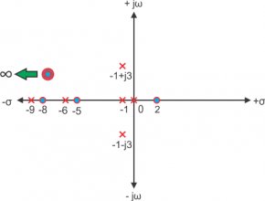 As the number of zeros should be equal to number of poles, the remaining three zeros are located at s →∞.
Example of Transfer Function of a Network
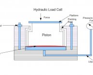
3) Answer In the above network it is obvious that Let us assume, Taking the Laplace transform of above equations with considering the initial condition as zero, we get,The Effect of Impulse Signal
The unit impulse signal is defined as Laplace transform of unit impulse function is 1. Now if input signal is unit impulse signal then, The output function is same as its transfer function.Share this article
Related Posts
Latest Posts


