Control Systems using MATLAB
This example shows how to use the Control System Tuner app to tune a MIMO, multiloop control system modeled in Simulink.
Control System Tuner lets you model any control architecture and specify the structure of controller components, such as PID controllers, gains, and other elements. You specify which blocks in the model are tunable. Control System Tuner parameterizes those blocks and tunes the free parameters system to meet design requirements that you specify, such as setpoint tracking, disturbance rejection, and stability margins.
Control System Model
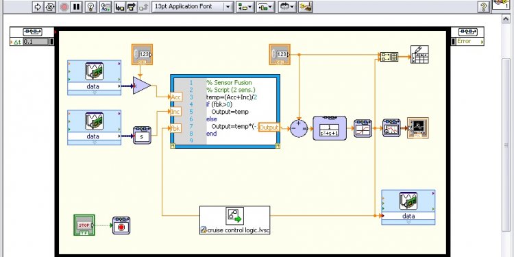
This example uses the Simulink model rct_helico. Open the model.
open_system('rct_helico')
The plant, Helicopter, is an 8-state helicopter model trimmed to a steady-state hovering condition. The state vector x = [u, w, q, theta, v, p, phi, r] consists of:
- Longitudinal velocity u (m/s)
- Normal velocity w (m/s)
- Pitch rate q (deg/s)
- Pitch angle theta (deg)
- Lateral velocity v (m/s)
- Roll rate p (deg/s)
- Roll angle phi (deg)
- Yaw rate r (deg/s)
The control system of the model has two feedback loops. The inner loop provides static output feedback for stability augmentation and decoupling, represented in the model by the gain block SOF. The outer loop has a PI controller for each of the three attitude angles. The controller generates commands ds, dc, dT in degrees for the longitudinal cyclic, lateral cyclic, and tail rotor collective using measurements of theta, phi, p, q, and r. This loop provides the desired setpoint tracking for the three angles.
This example uses these control objectives:
- Track setpoint changes in theta, phi, and r with zero steady-state error, rise times of about 2 seconds, minimal overshoot, and minimal cross-coupling.
- Limit the control bandwidth to guard against neglected high-frequency rotor dynamics and measurement noise. (The model contains low-pass filters that partially enforce this objective.)
- Provide strong multivariable gain and phase margins. (Multivariable margins measure robustness to simultaneous gain or phase variations at the plant inputs and outputs. See the loopmargin reference page for details.)
Set Up the Model for Tuning
Using Control System Tuner, you can jointly tune the inner and outer loops to meet all the design requirements. To set up the model for tuning, open the app and specify which blocks of the Simulink model you want to tune.
In the Simulink model window, in the Analysis menu, select Control Design > Control System Tuner.
In Control System Tuner, on the Tuning tab, click Select Blocks. Use the Select tuned blocks dialog box to specify the blocks to tune.
Click Add Blocks. Control System Tuner analyzes your model to find blocks that can be tuned. For this example, the controller blocks to tune are the three PI controllers and the gain block. Check the corresponding blocks PI1, PI2, PI3, and SOF.
Click OK. The Select tuned blocks dialog box now reflects the blocks you added.
When you select a block to tune, Control System Tuner automatically parametrizes the block according to its type and initializes the the parametrization with the block value in the Simulink model. In this example, the PI controllers are initialized to and the static output-feedback gain is initialized to zero on all channels. Simulating the model shows that the control system is unstable for these initial values.
Specify Tuning Goals
The design requirements for this system, discussed previously, include setpoint tracking, minimum stability margins, and a limit on fast dynamics. In Control System Tuner, you capture design requirements using tuning goals.
First, create a tuning goal for the setpoint-tracking requirement on theta, phi, and r. On the Tuning tab, in the New Goal drop-down list, select Tracking of step commands.
In the Step Tracking Goal dialog, specify the reference signals for tracking. Under Specify step-response inputs, click Add signal to list. Then click Select signal from model.
In the Simulink model editor, select the reference signals theta_ref, phi_ref, and r_ref. These signals appear in the Select signals dialog box. Click Add Signal(s) to add them to the step tracking goal.
Next, specify the outputs that you want to track those references. Under Specify step-response outputs, add the outputs theta, phi, and r.
The requirement is that the responses at the outputs track the reference commands with a first-order response that has a one-second time constant. Enter these values in the Desired Response section of the dialog box. Also, for this example set Keep mismatch below to 20. This value sets a 20% relative mismatch between the target first-order response and the tuned response.
This figure shows the configuration of the Step Tracking Goal dialog box. Click OK to save the tuning goal.
Next, create tuning goals for the desired stability margin requirements. For this example, the multivariable gain and phase margins at the plant inputs u and plant outputs y must be at least 5 dB and 40 degrees. Create separate tuning goals for the input and output margin constraints. In the New Goal drop-down list, select Minimum stability margins. In the Margins Goal dialog box, add the input signal u under Measure stability margins at the following locations. Also, enter the gain and phase values 5 and 40 in the Desired Margins section of the dialog box. Click OK to save the input stability margin goal.
Create another Margins Goal for the output stability margin. Specify the output signal y and the target margins, as shown, and save the output stability margin goal.
Share this article
Related Posts

Latest Posts


