Troubleshooting irrigation controller Systems
Too often, golf course irrigation system problems are not identified until it's too late. Suddenly, you're faced with a large area of stressed or burnt-out turf on your course and no way to bring it back to life. Even with the most advanced irrigation installations, there will be times where controllers, system wiring or valves will fail to operate according to the automated plan. Your sprinkler heads will sit there idle, waiting for instructions.
When an irrigation system goes on strike, the tendency is to look for a quick solution to bring the distressed areas back on line as soon as possible. Inexperienced technicians often focus their efforts on the most visible component in the system, the irrigation controller, placing the blame on a perceived problem within the complex electronics of the system's brain. It's a comforting thought that perhaps the irrigation can be revived by just changing out a few components within the controller, or the entire unit, as a way to quickly remedy the problem.
However, this method is generally a waste of time. Even though expensive components may be changed out, the system will usually continue to misbehave after each attempt. And the technician will become more and more frustrated by this waste of time and efforts chasing an unidentified problem.
A better approach: Step-by-step troubleshooting
A better way to approach electrical system trouble shooting is with a step-by-step method that isolates and checks each of the irrigation components: the controller, the zone control valves and the wiring that connects it all together.
Step 1: Check the obvious.
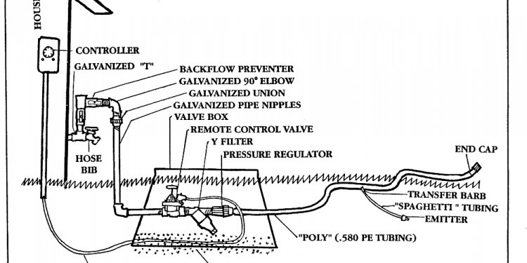
Before launching a thorough system diagnosis, don't forget to check the obvious. Is the system water supply on? Are there isolation valves at the backflow preventer, pump station or in the mainline that are preventing water from flowing? Has the flow control on the valve been turned off? Has the “on/off/auto selector” on a valve-in-head sprinkler been left in the “off” position? Reviewing these factors up-front can save time and effort.
Step 2: Make sure you don't have a programming error.
If the zone operates fine manually using the controller's manual mode, but does not operate automatically, this usually indicates a programming error rather than an electrical problem. Review the controller's programming guide and look for data-entry mistakes.
Step 3: Know how to use a volt-ohm meter.
An inexpensive volt-ohm meter (VOM) will be your most valuable tool and a required component for successful electrical troubleshooting. VOMs can be purchased in the electrical-supplies section of a local hardware store, electronics shop (such as Radio Shack) or your local irrigation equipment supplier. Modern digital meters are more reliable and provide an easy-to read display that can give precise quantitative feedback of the system symptoms.
Step 4: Is the controller operational?
After these preliminary steps, you're now ready to check the controller itself. A blank LCD display or failure to respond to keyboard entries could indicate a lack of power to the unit or other damage. Begin by using your VOM to take a voltage reading of the primary incoming power to the controller. It should read somewhere between 110 to 125 volts. If it doesn't, you've found your problem. Unfortunately, it's seldom that easy.
In some cases, you'll notice that the display of the controller is scrambled, missing LED segments or the entire unit is “frozen” preventing buttons or dials from entering data. This is a symptom of “micro-processor lock-up, ” where the primary brain of the controller has become confused with bad data from electrical surges or other causes. This can often be cleared by re-setting the device. Reset the controller by either disconnecting all electrical and battery power from the unit for several minutes, or by pressing a “reset” button which clears the memory of the processor and re-boots the system.
Step 5: Check for a tripped circuit breaker or blown fuse.
If the controller passes these tests, next check the station output of the controller to the valves that control the zones not receiving water. Again using the VOM, you can check to see if the output terminals indicate the 24 volts needed to open a standard solenoid. If you do not get a reading here, you should check for a blown fuse or tripped circuit breaker within the controller. Also check the output of the transformer in the controller to make sure that it is outputting correct voltage.
Share this article
Related Posts

Latest Posts


