Expert Answer

Closed loop response


Whenever you design a control system you will need to be able to predict the behavior of the system you design. There are a number of ways of predicting behavior, including using a simulation (in Simulink, for example, but any other simulator as well), using root locus or Bode' plot calculations, etc. However you do the prediction, you will need to have a model of the system. In many cases, the only way you can get a model is to take data on the system and try to fit a model to your data.

When you take data on a system, there are three choices.

  • You can input an impulse, a step or a ramp and analyze the time response to get the transfer function.
  • You can input a sequence of sinusoids and use gain and phase shift information to determine the transfer function from the frequency response.
  • You can input random noise (or many other signals) and use FFT techniques to get a frequency response, and then determine a transfer function from the frequency response.
  • Let's start by looking at a simulated system. If you you will get access to a simulator. It simulates a system and shows the unit step response of the system. Your goal is to determine the transfer function of the system. Your first task is to do the following.
  • Start the simulator.
  • Input a step. Repeat that experiment, and try changing the input step size.
  • Print a copy of the graph that results. You will need to pick off some numbers from that graph.
  • As you get started, here are some ideas for using the lessons, and this introductory lesson in particular.
  • Print this web page. If you print it you will have all of the questions ready for when you run the simulations.
  • Print the instructions for the simulator.
  • If you take that approach, you should be able to keep the simulator in view the entire time, and use the printed questions and instructions to work from.
  • Question(s)

    Q1. With the step response graph in front of you consider this question.

    Is the system first order, second order or some higher order system?


    Now, let us assume - for the moment - that the system is second order. The reason for making that assumption is simple.
  • The system exhibits oscillations that die out. Because of that, the simplest system that exhibits that behavior is a second order system.
  • In addition, there are no peculiar behaviors that would indicate that this was a higher order system.
  • z = Damping Ratio,
  • wn= Undamped Natural Frequency,
  • Gdc= The DC Gain of the System.
  • In order to calculate those three parameters you need to understand what each parameter influences in the step response. In the link above, you can find the following.
  • z, the damping ratio, will determine how much the system oscillates as the response decays toward steady state.
  • wn, the undamped natural frequency, will determine how fast the system oscillates during any transient response.
  • Gdc, the DC gain of the system, will determine the size of steady state response when the input settles out to a constant value.
  • However, you need to know precisely how each of those parameters influences those properties of the response.

    We will work first to determine the damping ratio. We know:

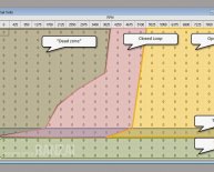
    In particular, one measure of how the response decays is to look at the overshoot in the step response. As a system has more overshoot, that system has less decay per cycle (and that applies to the first cycle where the overshoot occurs) and is indicative of a smaller damping ratio. The link above will take you to an extended discussion of overshoot and damping ratio in second order systems, but the primary result is encapsulated in a plot of overshoot versus damping ratio. That plot is shown below. Now, let's go back to the problem at hand. You still need to get the system to behave. Can you think of a way to control this system? Try to answer this question before going on, even if your ideas do not correspond with the options below.

    Actually, we were trying to get you to the concept of ON-OFF Control. It's a common way of controlling things like temperature in your house. The essence of ON-OFF Control is to apply maximum control effort when the system is below where you want it to be, and minimum control effort when the system is above where you want it to be. In the home thermostat that means your thermostat turns the heat ON when the house is tool cold and it turns the heat OFF when the house is too warm.

    In the simulator, we assume that the motor is driven by an amplifier that saturates in both directions. So, when the motor is going too slow, the simulator is max positive output - to increase the motor speed. When the motor is going too fast, the simulator is max negative output to make the motor start to slow down. Try that in the simulator. Do the following.

  • Click for Closed Loop to show the control loop.
  • The control loop has a comparator that checks whether the motor speed is above or below the desired speed and applies the correct voltage to the simulated motor.
  • You can set the desired speed using the input text box.
  • The control effort is shown in a separate plot. Note that the scale for the control effort is shown on the right hand side of the plot, and that scale is not the same as the scale for the output.
  • A Side Note

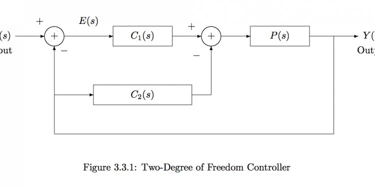
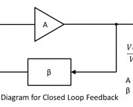
    In the ON-OFF control system the system is represented pictorially with a block diagram that shows how signals flow within the system and how they are processed.

    For an ON-OFF controller, the controller reacts to the error in the system. The error is the difference between what you want and what you have. The simplest ON-OFF controller is the home thermostat, which looks at the temperature you want, and the temperature it senses and turns the heating system ON or OFF, depending upon the error in the system. When the error is positive (i.e. the desired response is larger than the measured response) the controller turns the control effort to full ON. Otherwise, when the error is negative, the control effort is OFF. Some ON-OFF systems don't turn the control OFF when the error is negative. If the system is a motor, and you are trying to get to some predetermined speed, if you go past the desired speed, rather than turning the control effort to OFF, the control effort becomes that maximum possible negative control effort - which will tend to slow the motor down.

    Now, it's time to examine what happens when you implement ON-OFF control. Our simulator will let us examine what happens.


    Share this article


    Related Posts


    Closed loop systems
    Closed loop systems
    Closed loop feedback
    Closed loop feedback
    Closed loop function
    Closed loop function

    Latest Posts
    System Controls Technology Solutions Pvt Ltd
    System Controls…
    Bosch Chassis Systems India Pvt. Ltd…
    Sequential control definition
    Sequential control…
    Summary: In interface design favor direct…
    Solar system controller
    Solar system…
    What follows is a summary of our white…
    Types of Electrical control Systems
    Types of Electrical…
    Before I introduce you the theory of…
    Adaptive Cruise control Systems
    Adaptive Cruise…
    Two companies are developing a more advanced…
    Search
    Featured posts
    • Closed loop systems
    • Closed loop feedback
    • Closed loop function
    • Closed loop process control
    • Closed loop feedback system
    • Closed loop systems Examples
    • Closed loop control diagram
    • What is closed loop and open loop?
    • Closed loop temperature control
    Copyright © 2024 l www.oliver-control.com. All rights reserved.