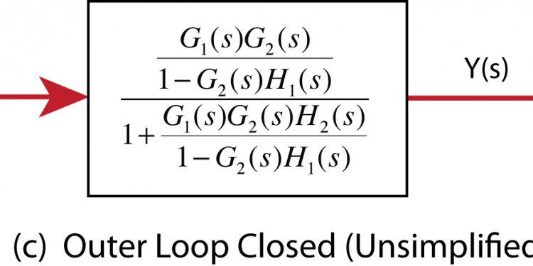
Open loop block diagram
Compute a linear model of the combined controller-plant system without the effects of the feedback signal. Use a Bode plot of the resulting linear model to see the open-loop response.
Open Simulink model.
sys = 'watertank'; open_system(sys)
The Water-Tank System block represents the plant in this control system and contains all of the system nonlinearities.
In the Simulink Editor, define the portion of the model to linearize:
- Right-click the PID Controller block input signal (the output of the Sum block). Select Linear Analysis Points > Input Perturbation.
- Right-click the Water-Tank System output signal, and select Linear Analysis Points > Open-loop Output.
Annotations appear in the model indicating which signals are designated as linearization I/O points.
Open the Linear Analysis Tool for the model.
In the Simulink Editor, select Analysis > Control Design > Linear Analysis.
By default, the I/O points you specified in the model are the selected Analysis I/Os for linearization, as displayed in the Analysis I/Os menu.
Linearize the model with the specified I/Os, and generate a Bode plot of the linearized model.
Click Bode. The Bode plot of the linearized plant appears.
Tip Instead of a Bode plot, generate other response types by clicking the corresponding button in the plot gallery.
View the minimum stability margins for the model.
Right-click the plot and select Characteristics > Minimum Stability Margins.
The Bode plot displays the phase margin marker. Click the marker to show a data tip that contains the phase margin value.
Share this article
Related Posts
Latest Posts


